7 IO & Summary
Input/Output Devices
Bus: Common set of wires for communication among hardware devices plus protocols for carrying out data transfer transactions
- Operations: e.g., Read, Write
- Control lines, Address lines, Data lines
Two types of Disks:
- Magnetic Drives: Information stored by magnetizing ferrite material on surface of rotating disk
- Flash Drives(Solid State Drives and Thumb Drives): Information stored by trapping charge in a semiconductor and MOSFET based dualgate transistor
HDD
Actuator moves head (end of arm) over track ("seek"), wait for sector to rotate under head, then read or write
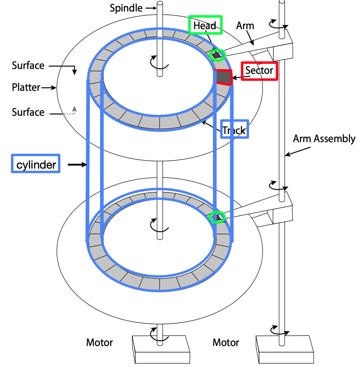
Disk Access Time = Seek Time + Rotation Time + Transfer Time + Controller Overhead
- Seek Time: time to position head to correct track
- Average Seek Time = 1/3 time for the head to cross all tracks
- Rotation Time: time for disk to rotate to proper sector
- Average rotation time = 1/2 time of a rotation
- Transfer Time: time for data to rotate under the head
HDD Scheduling
- FIFO
- Pro: Fair among requesters
- Con: order of arrival may be to random spots on the disk(Very long seeks)
- SSTF(Shortest seek time first): Pick the request that’s closest to head
- Pro: Reduce seek time, throughput increases
- Con: may lead to starvation
- SCAN(aka elevator): Take the closest request in a particular direction. When reaches the end, it reverses direction and follow the closest request.
- Pro: no starvation
- Con: Long waiting time for locations just visited by disk arm
- C(Circular)-SCAN: only goes in one direction, skips any requests on the way back
- Pro: A bit more fair to inner and outer tracks
SSD
Pros (vs. hard disk drives):
- Low latency, high throughput (eliminate seek/rotational delay)
- No moving parts: Very light weight, low power, silent, very shock insensitive
- Read at memory speeds (limited by controller and I/O bus)
Cons
- expensive (3-20x disk)
- Limited drive lifetime
IO Communicating
Processor accesses registers in two ways:
- Port-Mapped I/O: in/out instructions
- Memory-mapped I/O: load/store instructions
Here are 3 types of Memory-mapped I/O:
Polling
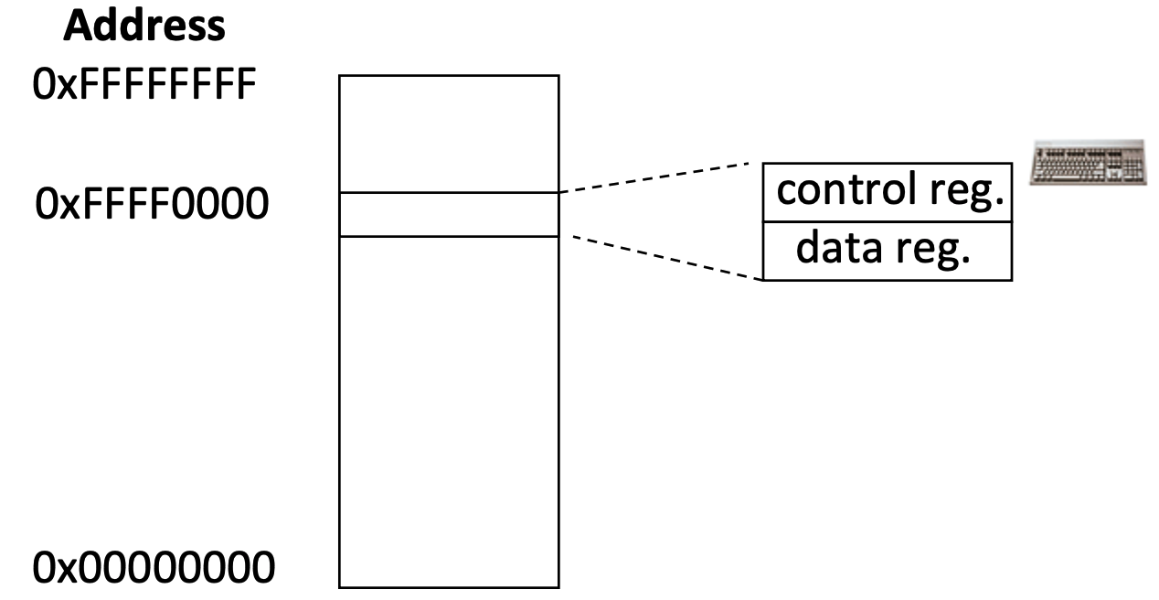
Path to a device generally has 2 registers:
- Control Register says it’s OK to read/write (I/O ready)
- Data Register contains data
Polling:
(1)Processor reads from control register in a loop, waiting for device to set Ready bit (0 → 1)
(2)Processor then loads from (input) or writes to (output) data register, resets Ready bit of control register (1 → 0)
Pro: low overhead
Con: may waste many cycles on polling if infrequent or unpredictable I/O operations
Interrupt
Device generates an interrupt whenever it needs service
- Pro: handles unpredictable events well, asynchronous to current program
- Con: interrupts relatively high overhead
Polling vs. Interrupts
Low data rate (e.g. mouse, keyboard)
- Use interrupts to avoid "waiting" for data
- Overhead of interrupts ends up being low
High data rate (e.g. network, disk)
- Start with interrupts
- Once you start getting data, switch to polling. Keep grabbing data until empty
DMA
Directed Memory Access:
- Device controller transfers data directly to/from memory without involving the processor
- Only interrupts once per page once transfer is done
Mechanism
- For incoming data, CPU receive interrupt from device; For outgoing data, CPU need to confirm that external device is ready
- CPU instructs DMA engine/device that data is available @ certain address
- Device/DMA engine handle the transfer, CPU is free to execute other thing
- Upon completion, Device/DMA engine interrupt the CPU again
Performance
Efficiency
- CPI: Clock cycles per Instruction
- MIPS: Millions of Instructions per Second
cpu time = Instructions CPI Clock cycle time
= Instructions * CPI / Clock rate
= Instructions / MIPS*10^6
Power and Energy
Total power = dynamic power + leakage power
Dynamic power activity capaictance voltage frequency]
Leakage power voltage
Energy = power time
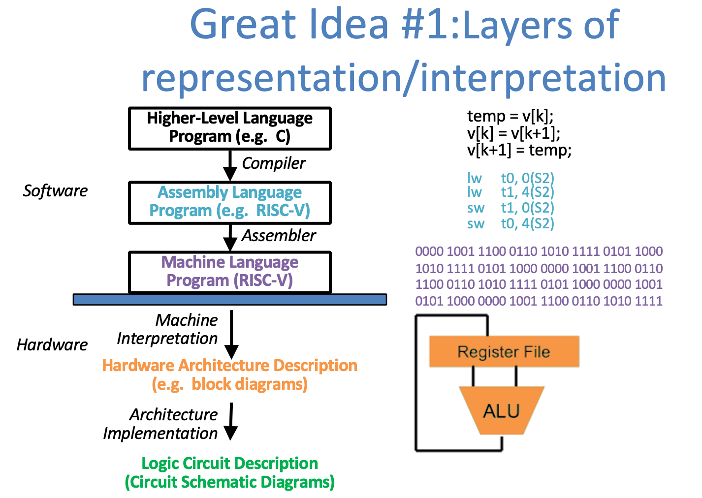
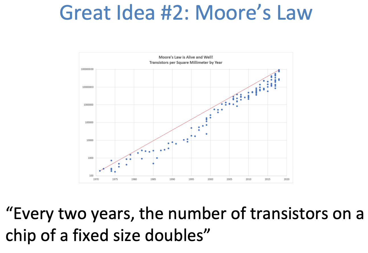
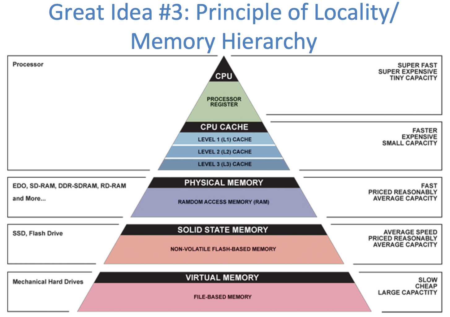
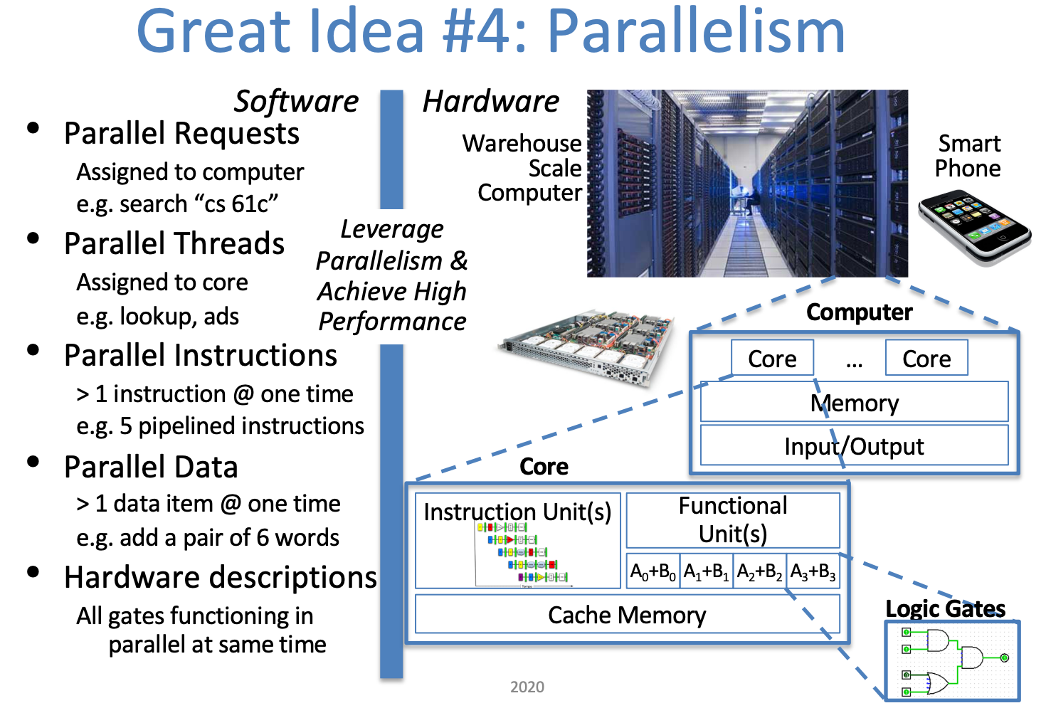
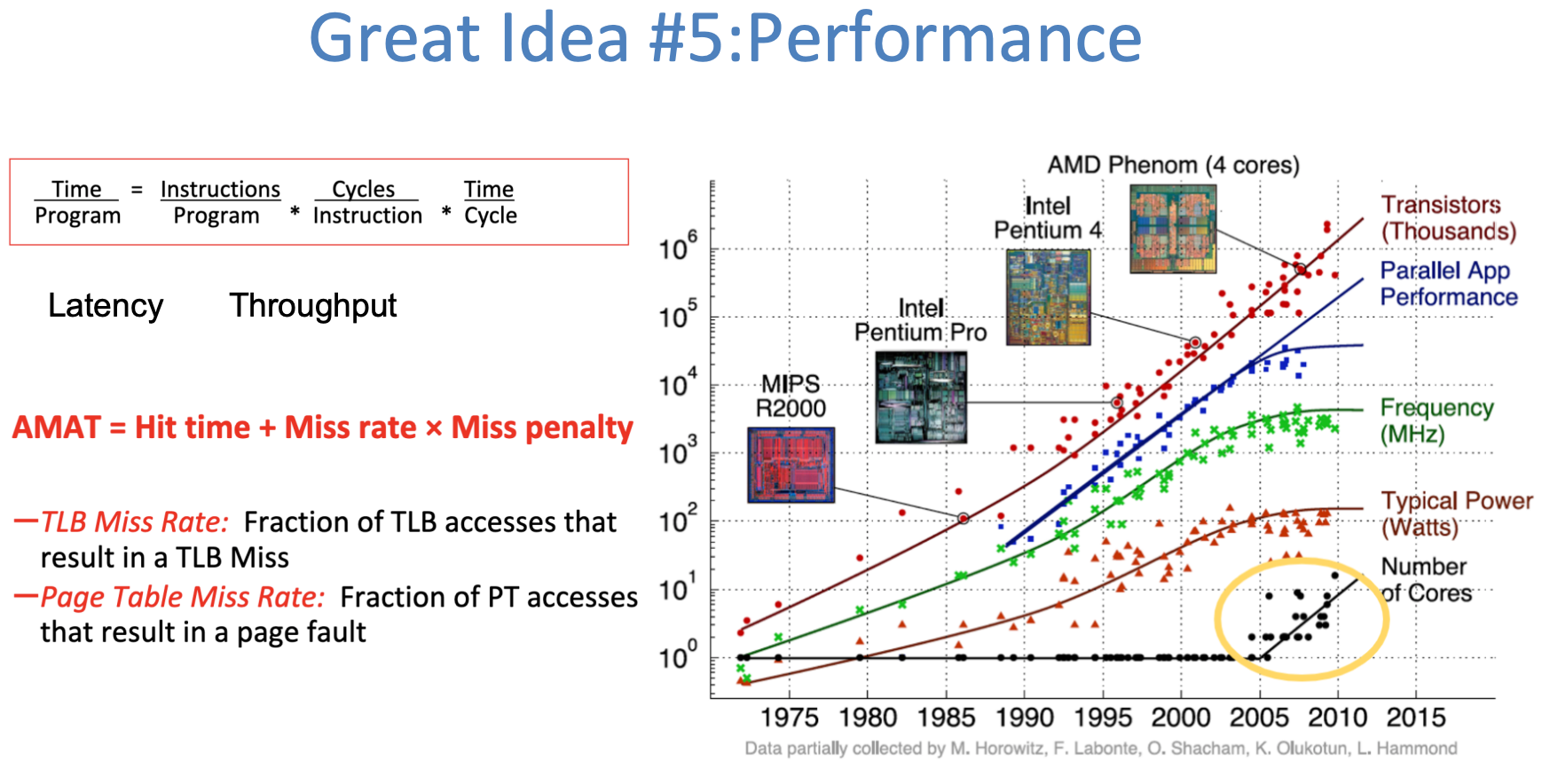
Five Great Ideas in Computer Architecture